
Little business’ software.
Endemiki.ru is our little family business. We design & produce plywood toys, souvenirs, home furniture. Our main production tool is cnc laser cutting machine based on Ruida controller. As we use to do everything ourselves, we need several software to realize our tasks:
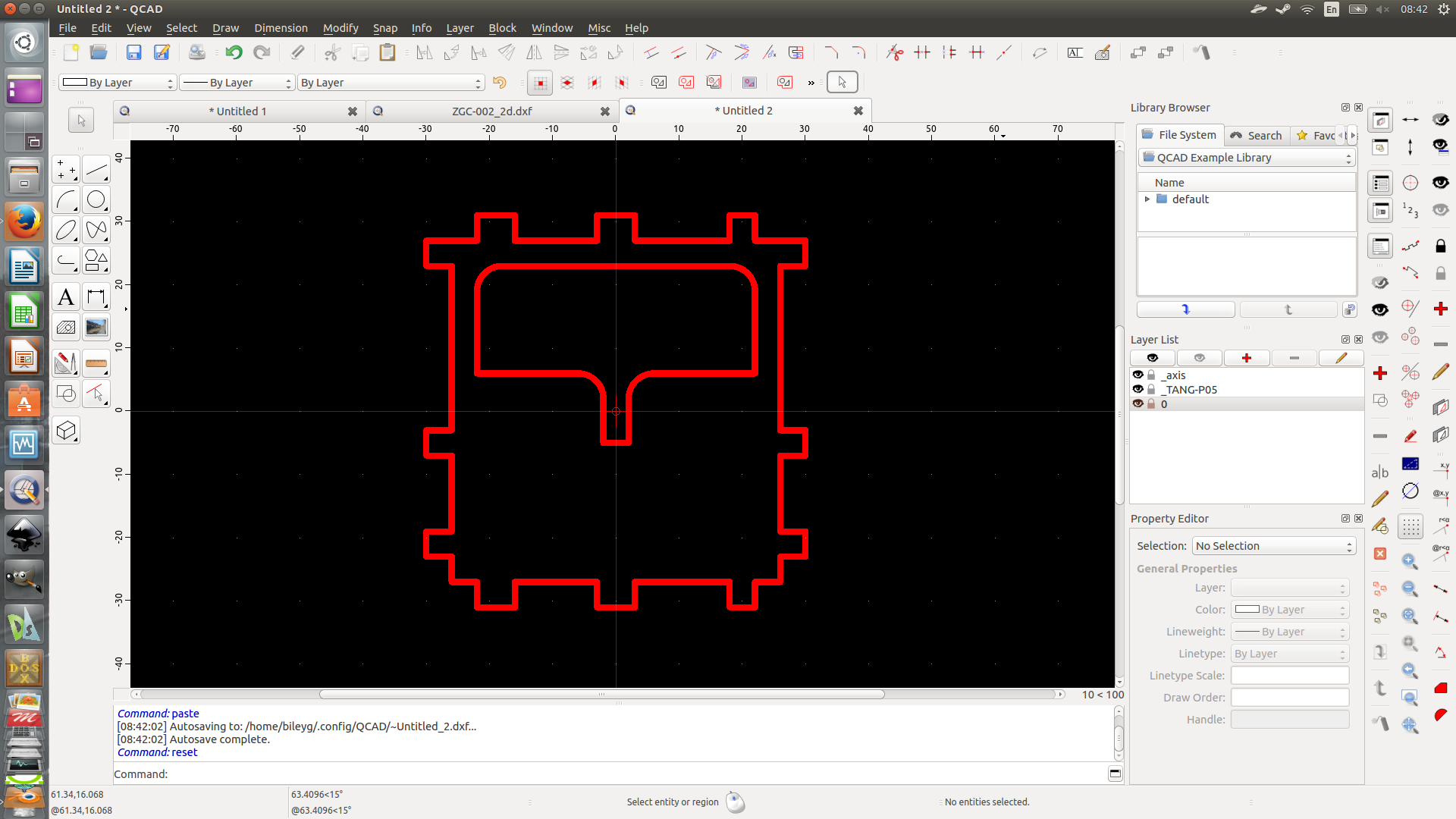
2d projecting/drafting
— dxf files are imported to controller of cnc laser machine to cut plywood.
3d projecting
— we assemble everything in 3d before cutting to exclude errors & make development faster.
raster image processing
— a lot of tasks: prepare image for engraving, edit picture to fit website, etc.
vector design processing
— design manuals or another method of cnc program input — svg import.
office program
— creating text and table documents to make company functional.
If we’d go traditional way we should spent a lot of money for all these propietary program products: MS Windows, MS Office, AutoCAD or Solidworks, Photoshop, Adobe Illustrator or CorelDraw. But we have choosen FREE way of LIBRE software. God bless GNU/GPL. Our choice allows us to create more economical production — we don’t have a need to add software wages to our prices.
Blender3d + QCAD = 3dCAD/CAМ sys
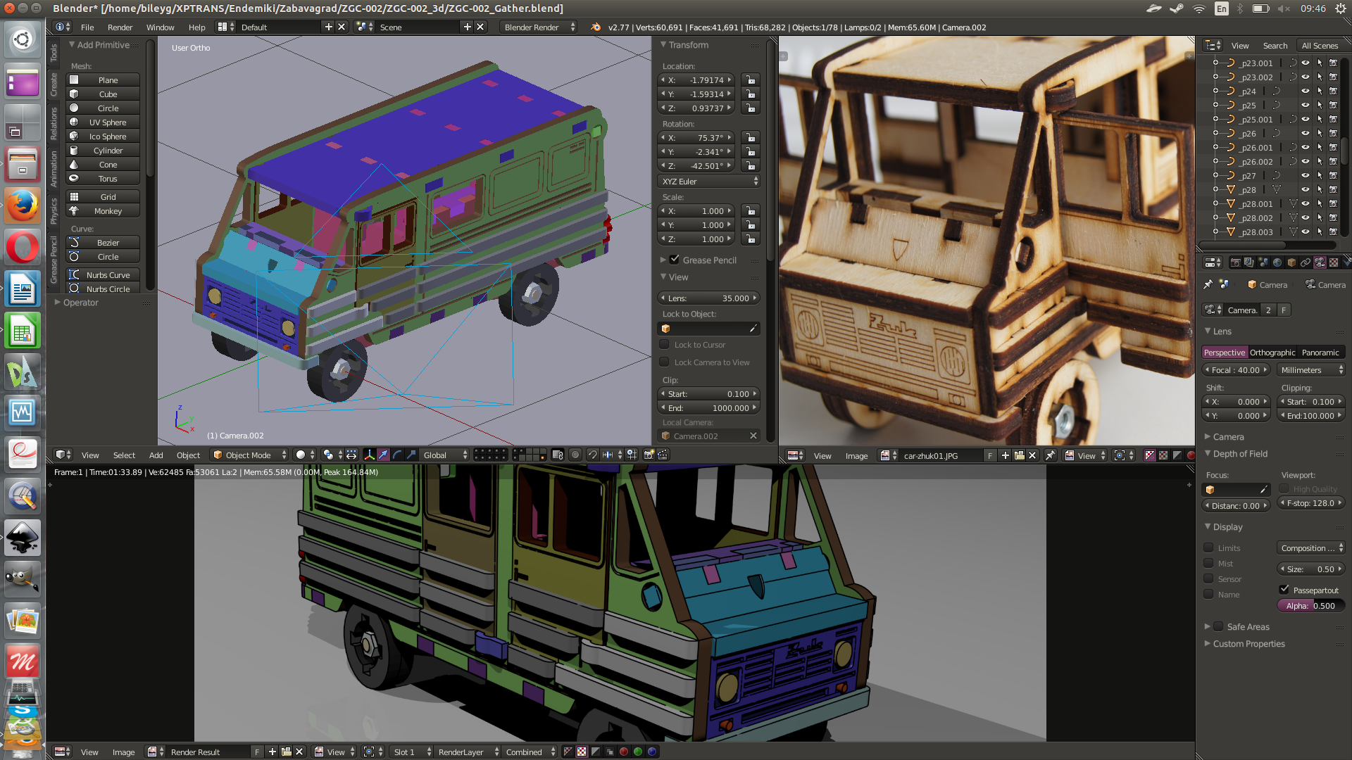
The main plot of this article is free 3dCAD/CAМ complex we’ve got combining the possibilities of Blender3d & QCAD. QCAD does everything about 2d for cnc cutting: technical drawings, detail schemes, final dxf-file to be imported by machine. Blender3d imports dxf details patterns & then does everything about 3d: details modelling, details assembling & then rendering for different purposes.
How to use Blender+QCAD bundle.
Step 0. Idea.
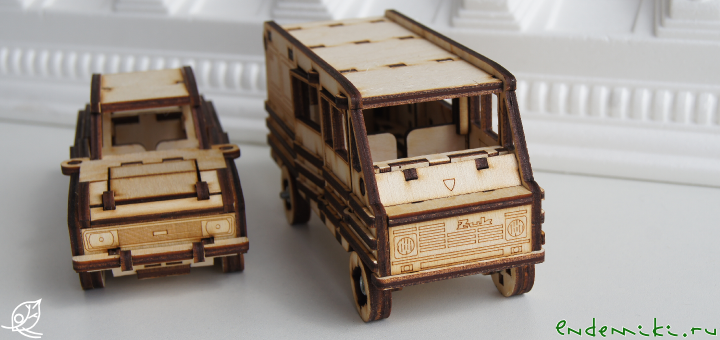
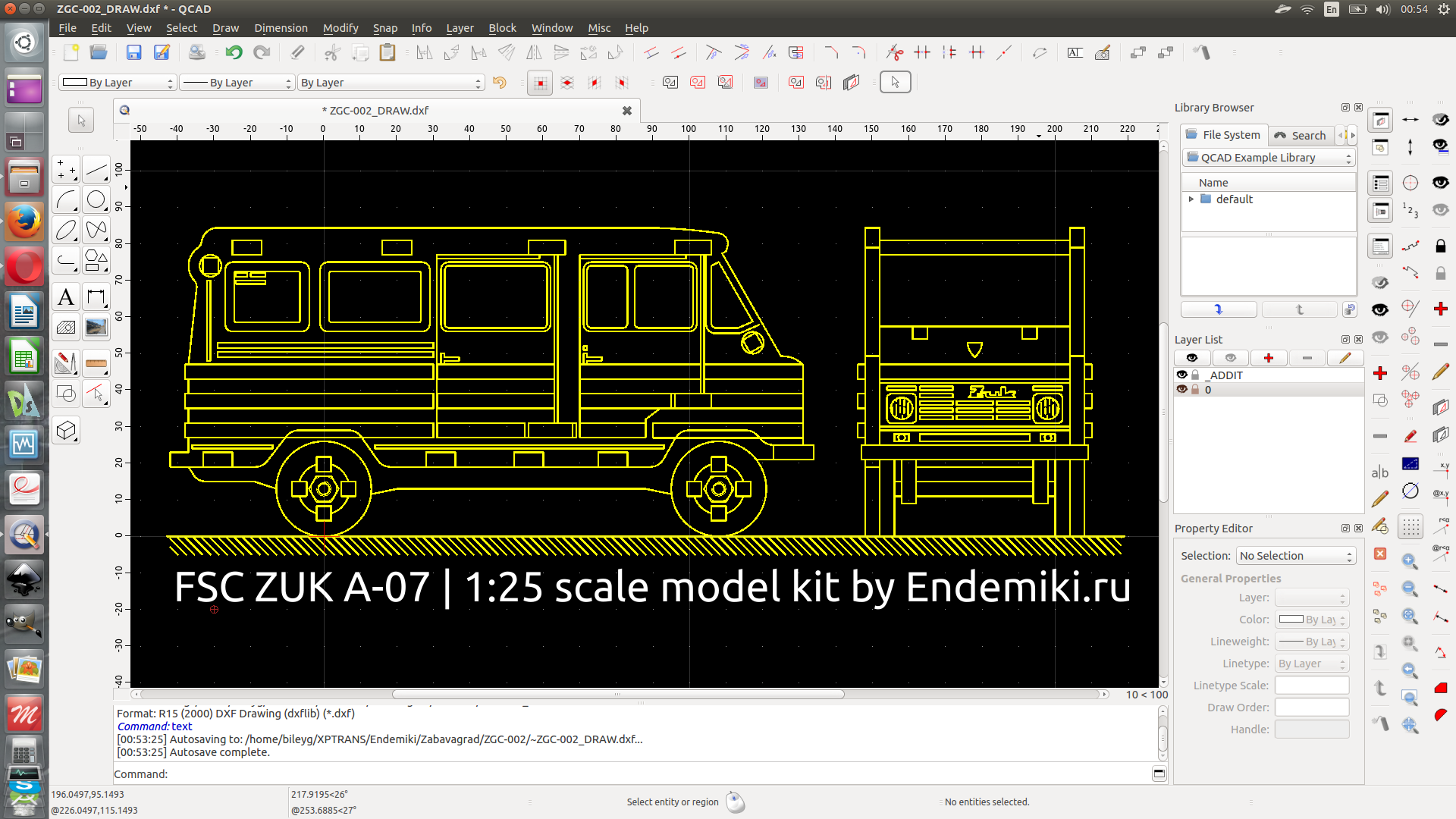
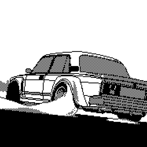
First of all, I need to choose the thing I want to design. For this case it will be the 1/25 scale model of funny polish van «Zuk A-07». So I found the blueprint of the car in Internet and use it as background to create this nice yellow blueprint in QCAD:
Step 1. 2d concept.
First of all I draw it 2d trying to create the conception as close to reality as possible. I don’t hope idea will be fine from the first try. Here’s a lot of thoughts at these moments & constantly mutating file.
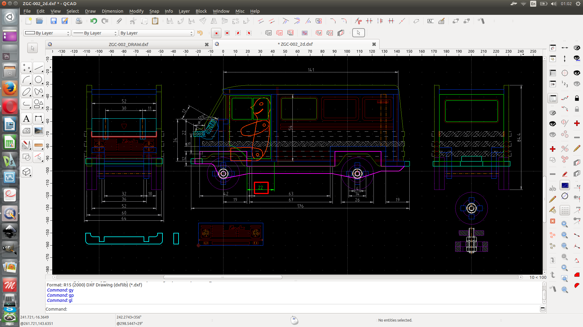
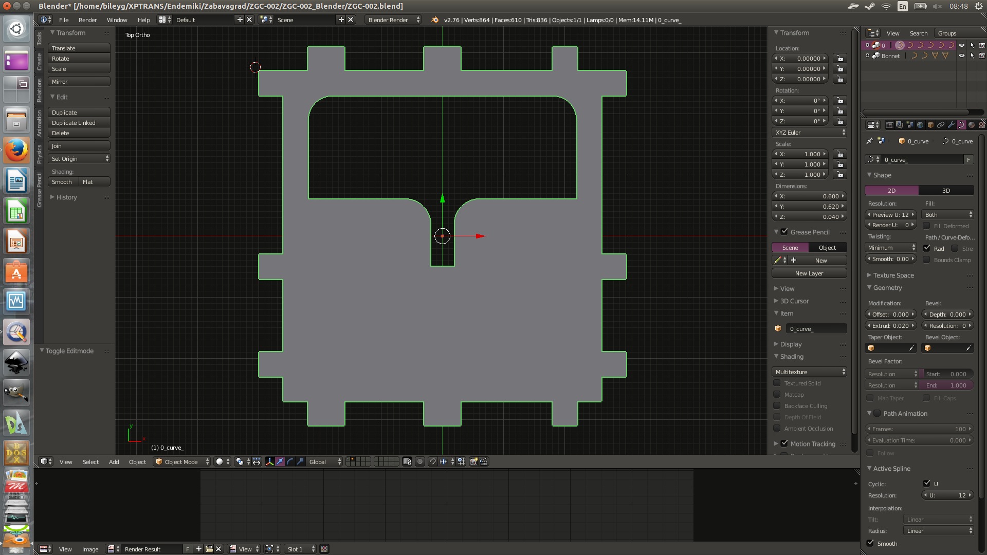
Step 2. Details.
After 2d concepting I start with detail engineering. I create special folders: one for dxf and another for blender files. Each detail has individual dxf & blend files. Blender preciously imports dxf if you know and use 2 simple rules: draw everything in polylines (circle is square polyline with rounded edges) and each polyline should be closed.
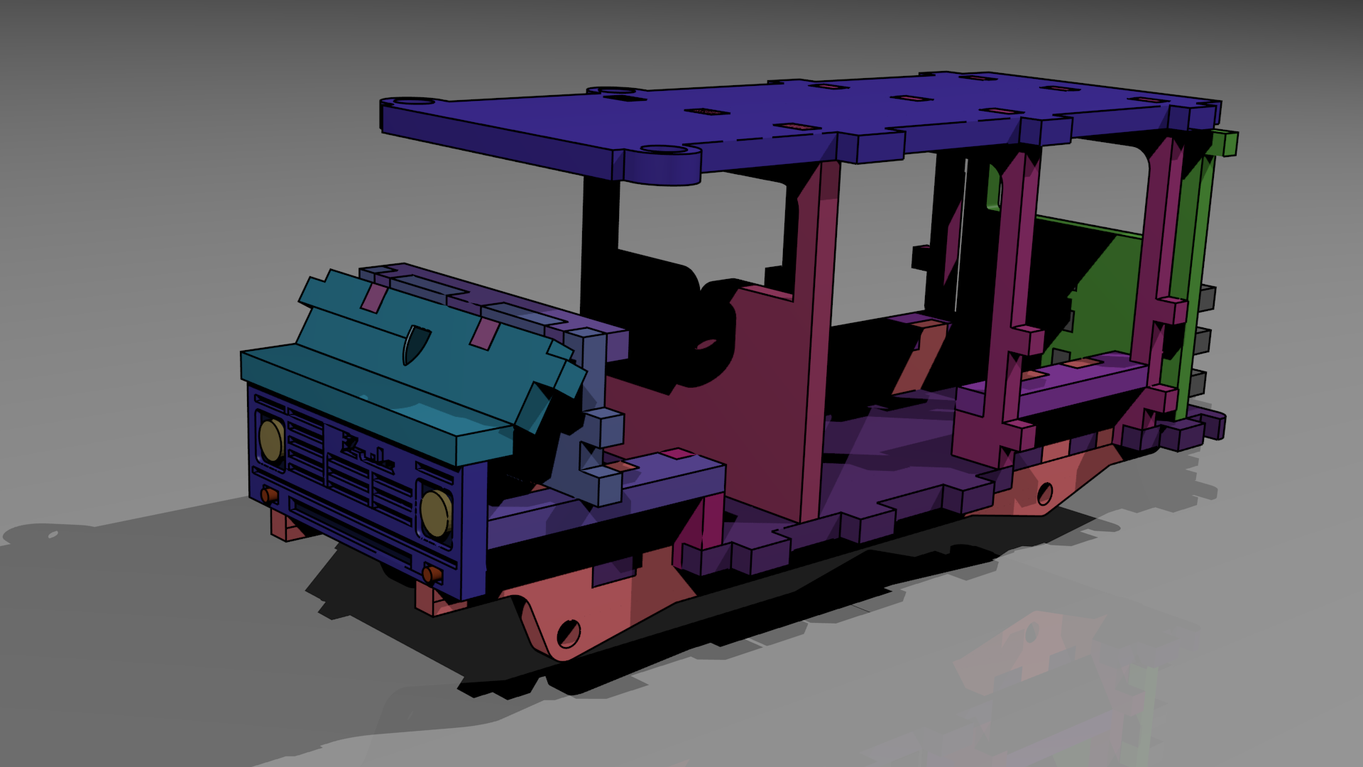
Step 3. Assemblage.
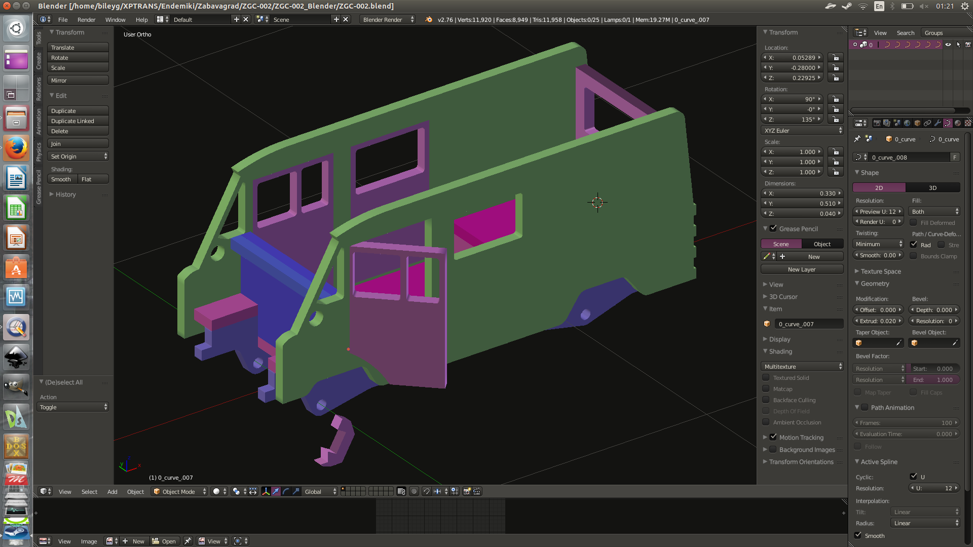
So I have some product parts. Each lays in individual file. Time to start assemble ’em! Create assemble file & link files with details. Starting this I use to see a lot of errors caused by misconnections of parts (that were overlooked in 2d). That’s the main purpose of Blender3d usage. I see the errors before we start cutting. And my preliminary assemblage goes to ideal step by step.
Step 4. Final DXF for CNC machine.
After my assemblage in Blender3d is finished-polished & I check all the possible misconnections & errors I could make final dxf file for our cnc laser cutting machine. It’s easy. I just create fresh-new file in QCAD and «ctrl-c» — «ctrl-v» all the details from my DXF folder to this new file. This way I have dxf file suitable to be imported to machine’s soft.

Step 5. Now we can cut.
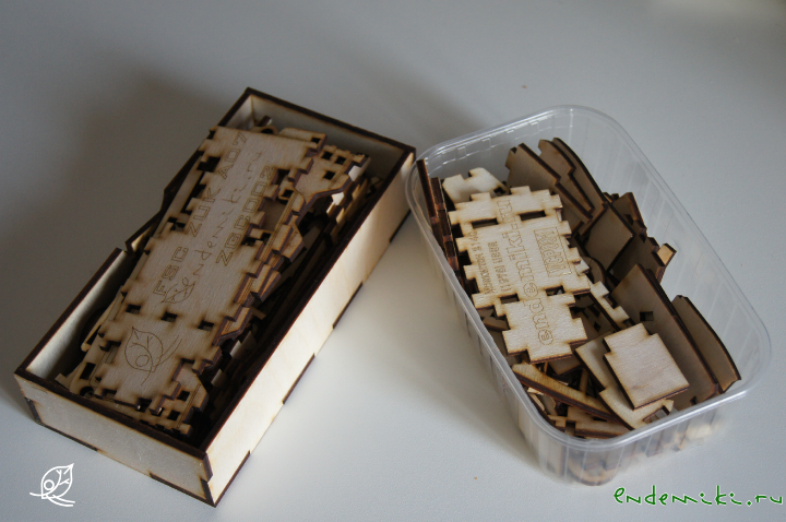
To cut details from plywood sheet is only the part of work. Kit is complex enough to require manual. So the next part of story will be about the manual preparation. And Blender3d will help us again
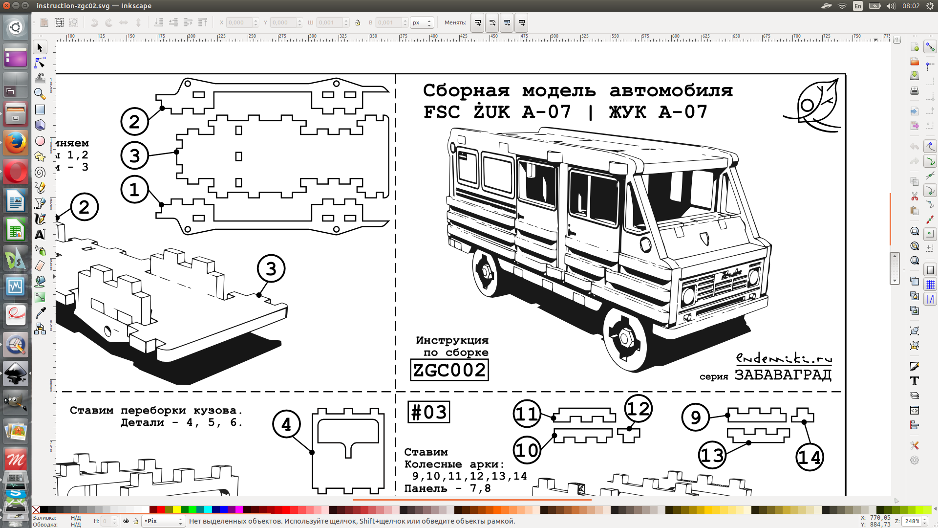
Creating manual for the kit
Manual should be on paper to be put to the kit’s box. 2 side monochrome printed sheet of common paper. We shall need also vector & raster image processing software to implement this micro publishing task. Long time ago we’d chosen Inkscape & Gimp. And we continue using ’em now.
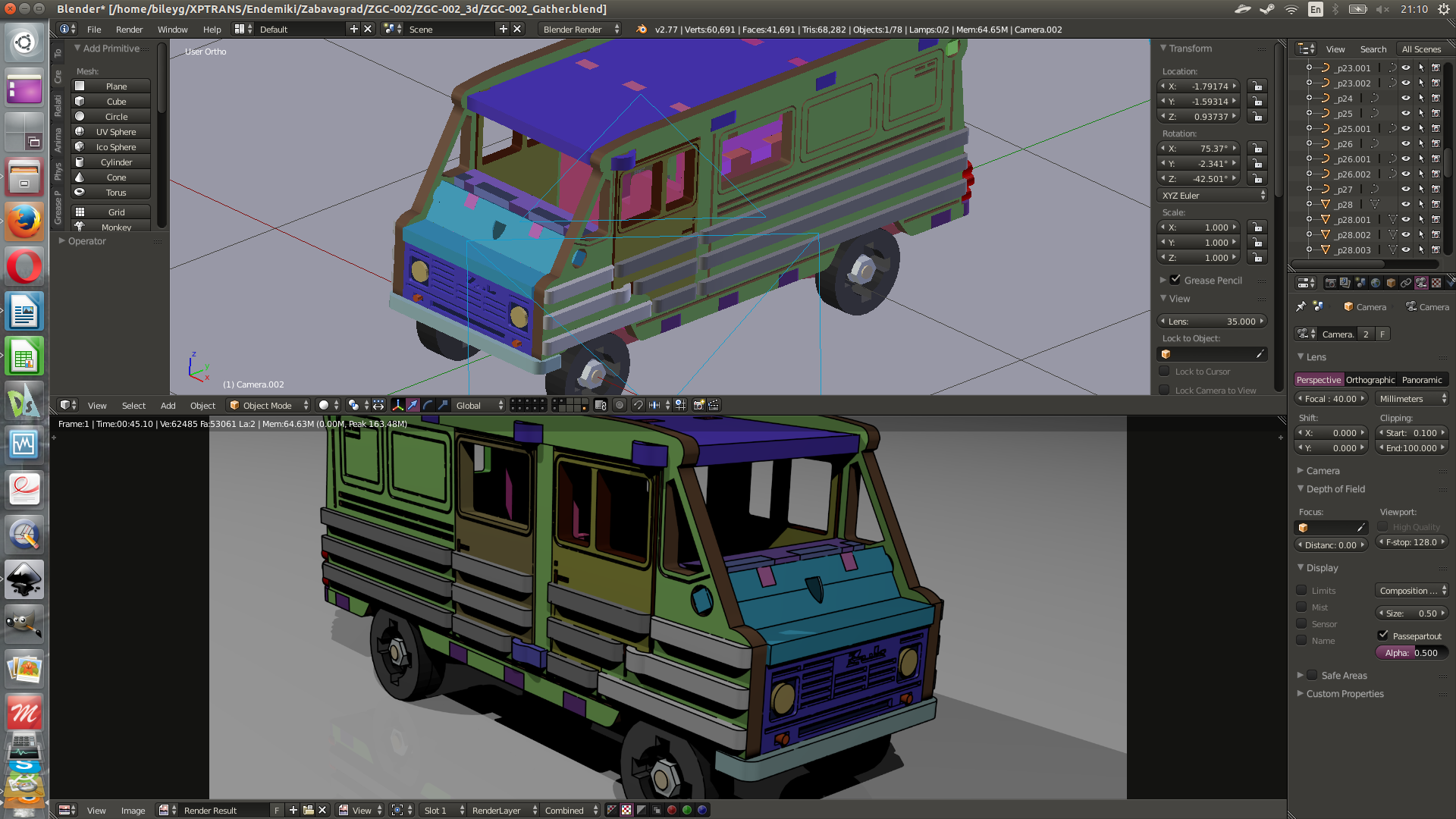
The source for our manual is 3d model made in Blender3d. I spread details by blender’s layers to each layer corresponds the certain step of assemblage. This way I can switch off all the layers and then switch on layer after layer I get step-by-step instruction looking like the set of technical renderings. See the pic below:
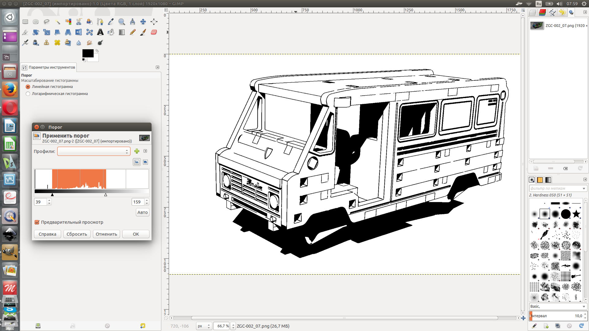
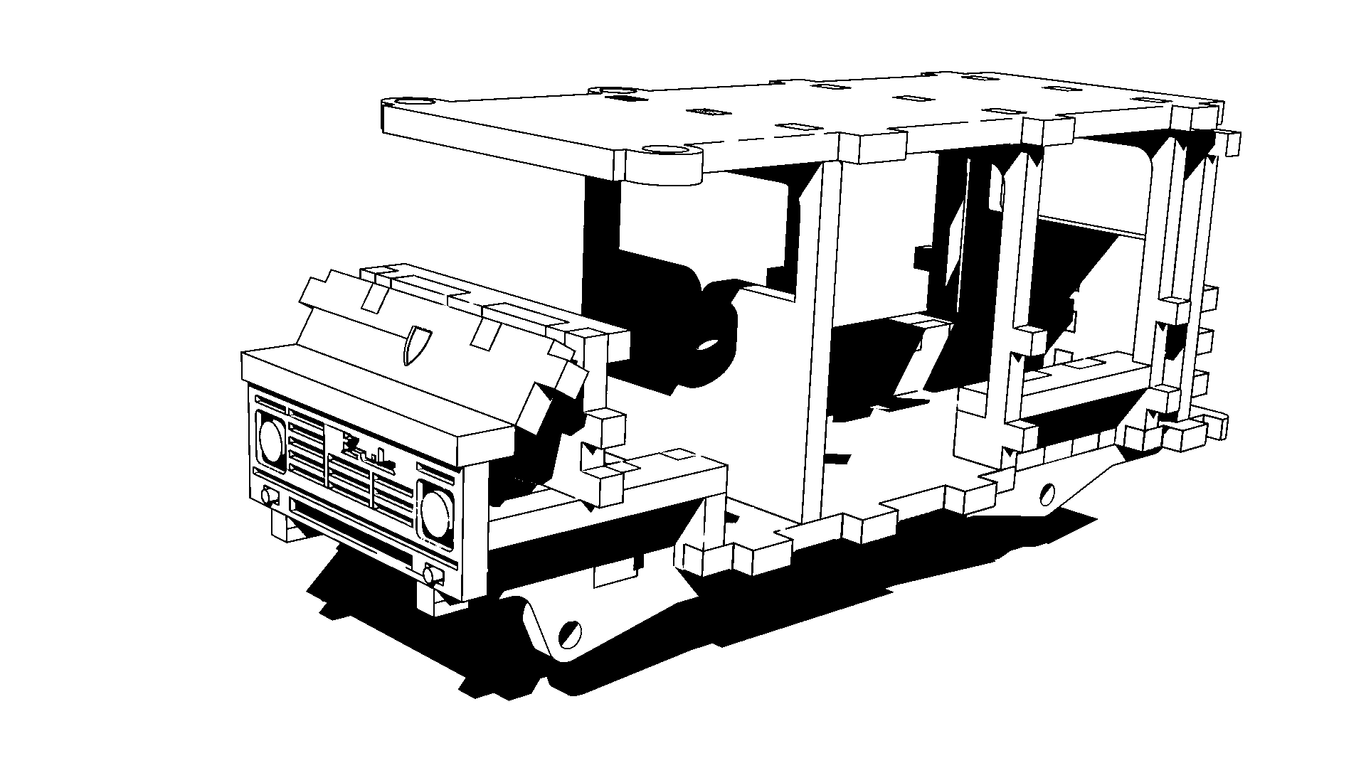
This pic needs to be processed. I thought it would be nice to get monochrome draft-like or technical scheme look (& also that’s why I implemented old-fashioned monofont). To make the color go away I opened the picture in GIMP and used simple «Threshold» adjustment. To get advanced knowledge about this tool[See GIMP help]
Raster image is not always the greatest feature for publishing. That’s why I vectorize image with Inkscape.
The time to arrange manual pictures and supply them with numbers and descriptions starts after all the monochrome images are vectorized. It’s definitedly the Inkscape work. Honestly said, I love Inkscape. It’s free, fast, light, clear and nice… and also it gives perfect result.
Finally the OS
Every program needs OS to work on. We use GNU/Linux system Ubuntu 14.04LTS. I wont number all the Linux advantages to avoid any holywar talks, but due to this article topic I should mark that Ubuntu is FREE. And also that my acknowledgement with GNU/GPL software (which are all listed above) started with Ubuntu.
Zero fee 3dCAD/CAM system is build
Zero fee 3dCAD/CAM system is build. The little family business saved by using GNU/GPL software. And the most important and happy notice:
It’s possible to use ONLY free (libre) software for rather serious work. I prove it!